Permanent mounting of the arch on Sérénité involved several steps. Here’s how the next phase of the project unfolded:
1. Final Fitting of the Arch:
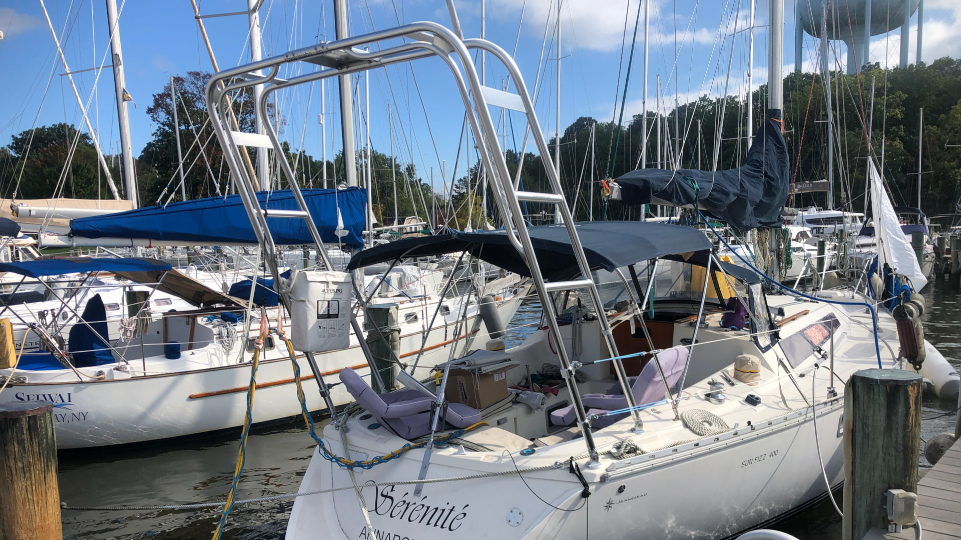
Final fitting of the arch involved standing the arch up on the back of the boat to see how the feet would land relative to the areas of newly reinforced deck, making any minor trims to the tubing, then marking locations for the feet.
2. Mounting the Feet to the Reinforced Areas:
The next step was to mount the arch feet onto the reinforced areas of the deck. The aft feet (seen in far left of top photo) needed to be mounted atop the aluminium reinforcing plates discussed in the previous post.
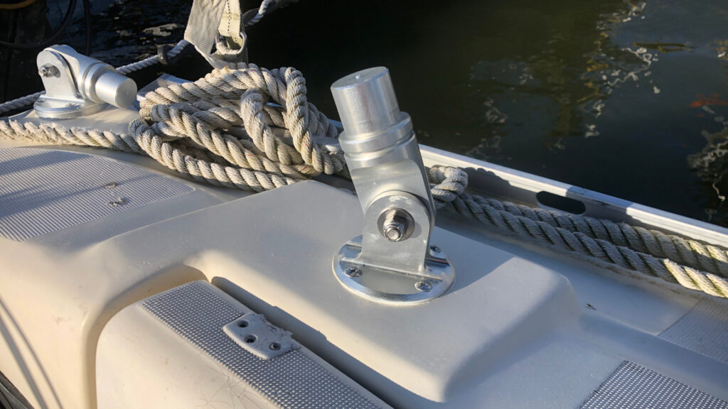
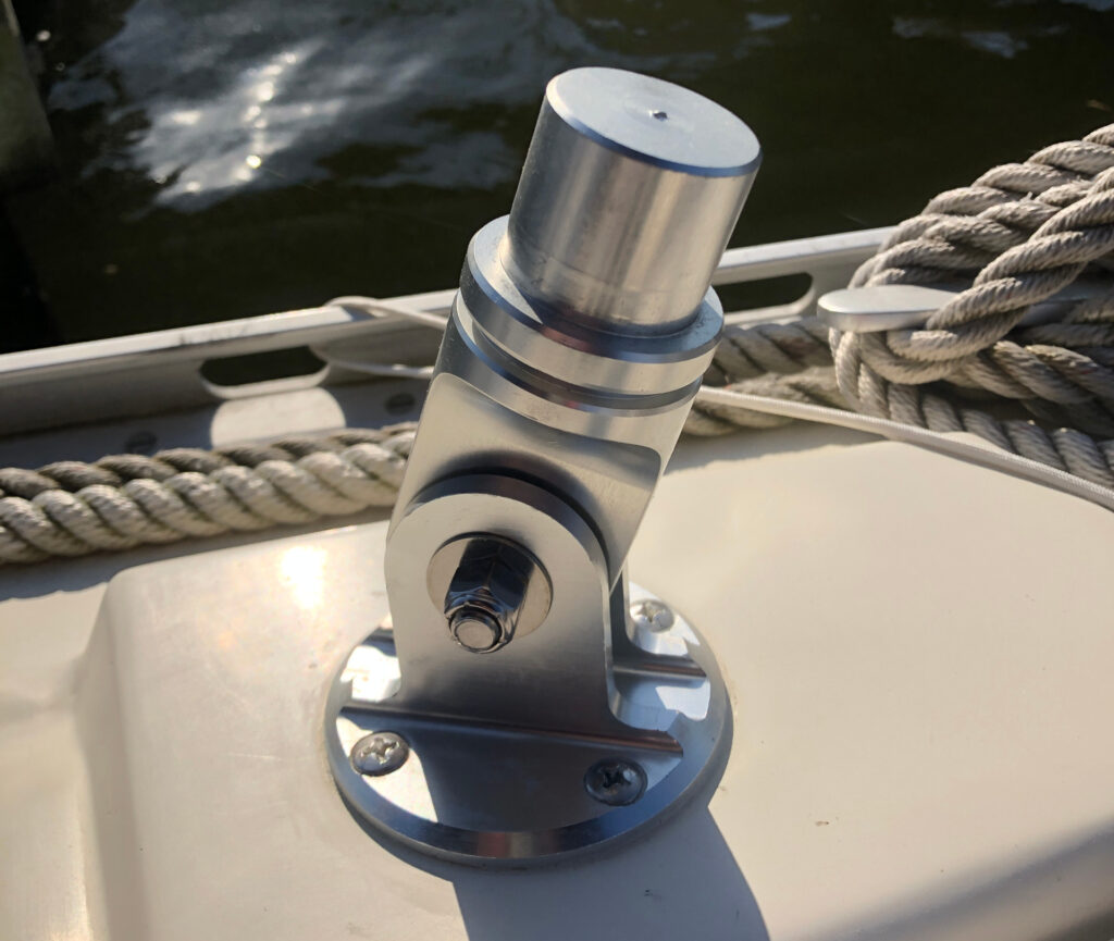
3. Tapping Holes for 1/4-20 Bolts:
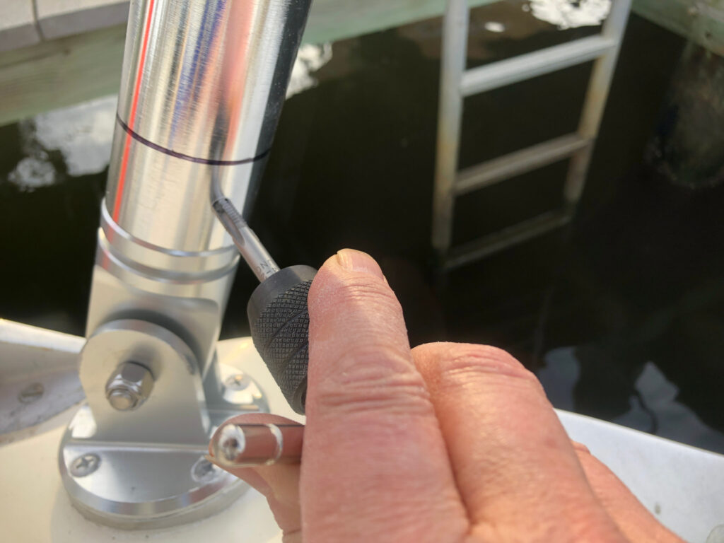
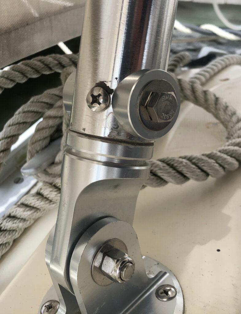
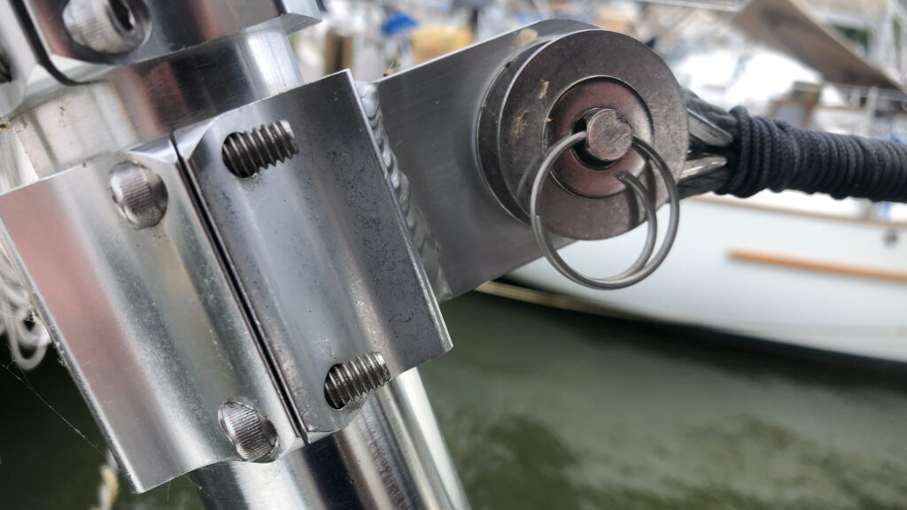
With the arch feet in place, the next task was to tap holes for the bolts that would both hold the arch in place while the epoxy sets, and provide a backup for the Epoxy. Three holes, equally spaced around the circumference, were tapped in each leg. the black line in the photo indicates the top of the inserted pin. I drilled and tapped the holes to at least 20mm to insure that the bolt would extend at least 10mm into the body of the pin.
4. Final Cleaning of Metal-to-Metal Contact Points:
After the holes were tapped, it was essential to clean the metal-to-metal contact points thoroughly. This step involved using acetone to remove any oil or debris from the tapping process. Then I used a Dremel tool with a conical grinder bit to rough up the inside of the tube and the pin (the portion of the foot assembly that slides into the tubing) Ensuring that these surfaces were clean and rough was essential to achieve a strong and durable bond.
5. Application of the Epoxy:
The final step in this phase was the application of epoxy to bond the tubing of the arch to the feet. The Marine-Tex epoxy included with the arch is the 5 minute variety so it’s imperative that you have everything ready so you can work fast – especially if it’s a warm day!
6. Oops! Safety Through-Bolts
On a subsequent call with the manufacturer (and after re-reading the instructions) there was a really important step I missed – the installation of the safety bolts in the forward legs… So, one of the 1/4-20 bolts was removed and an additional hole was drilled through the tubing and pin of the forward legs to install the safety bolt recommended by the manufacturer. The result is shown below.
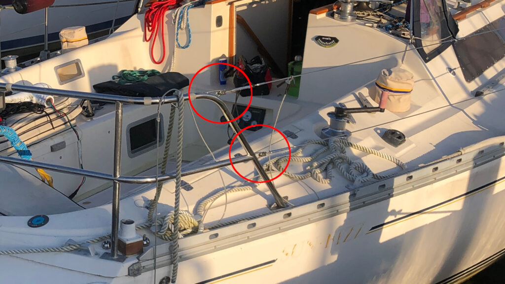
Reattaching the Lifelines
Since the original aft connection points for the lifelines were on the old railings (now removed) and the new connection points on the arch were much further aft, I basically had two choices: have new lifelines made or adapt my existing lifelines. Since I had just replaced Sérénité’s lifelines the previous year I decided on the latter.
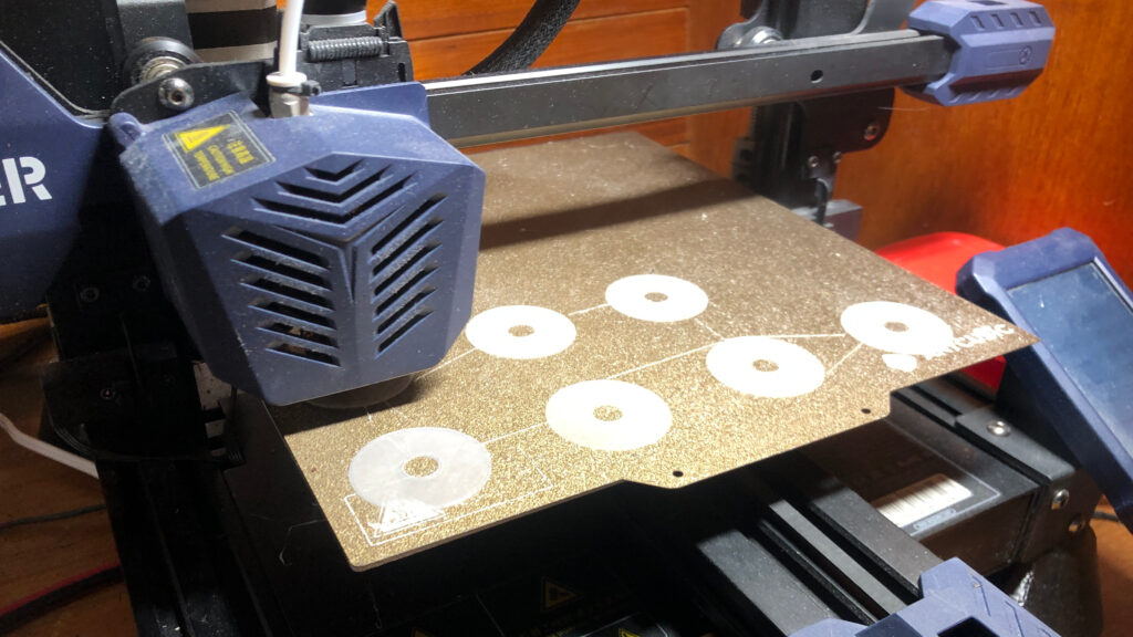
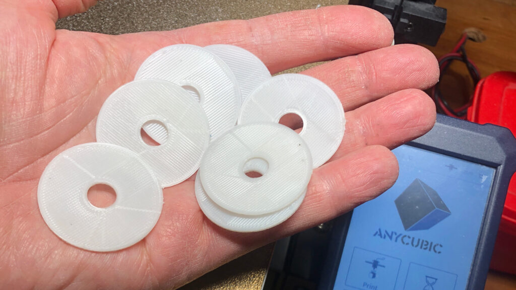
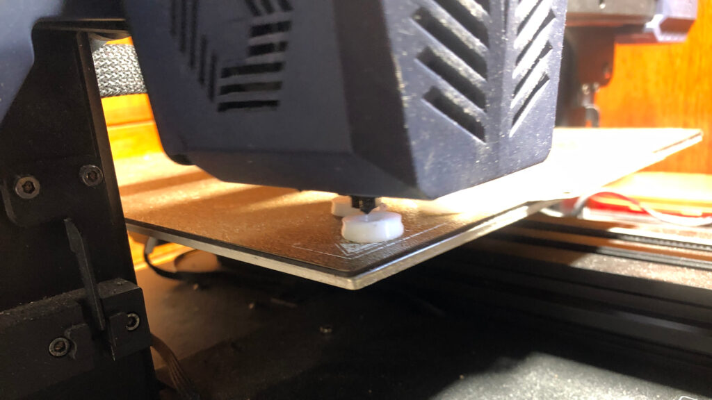
Design and Fabrication of Plastic Components:
The Using FreeCAD, plastic washers and pulleys were created for the lifeline extensions. Once the design was finalised the models were sliced using Cura and printed on Sérénité’s onboard 3D printer using nylon filament. The design of the plastic components is available in Sérénité’s PRS database should replacements be needed or for use in future projects.
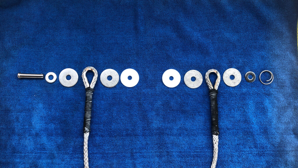
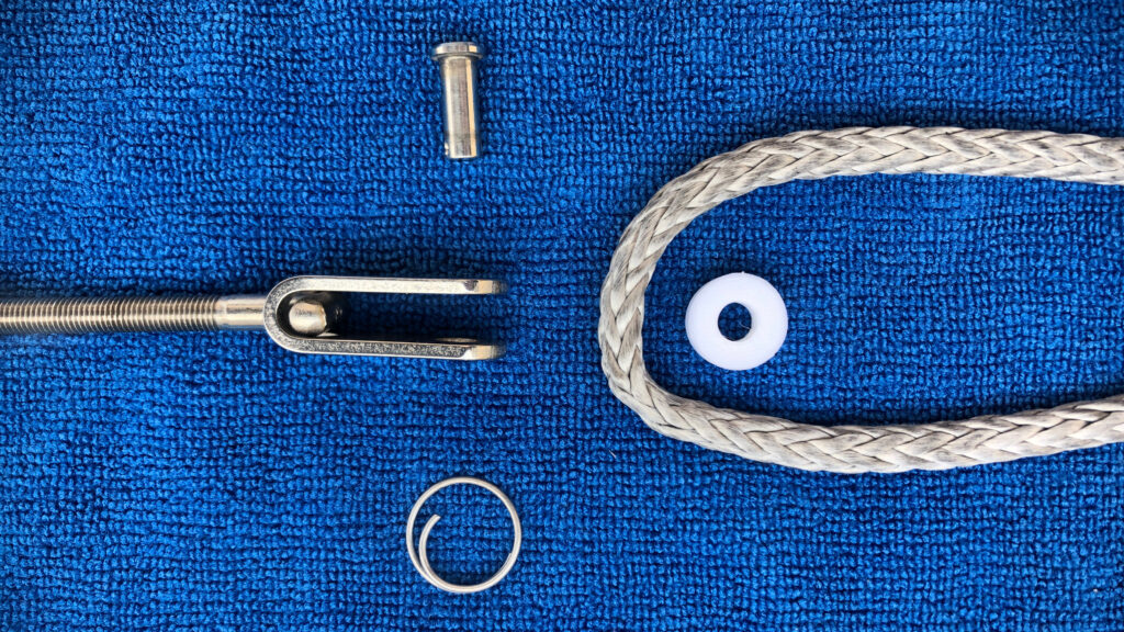
Assembly:
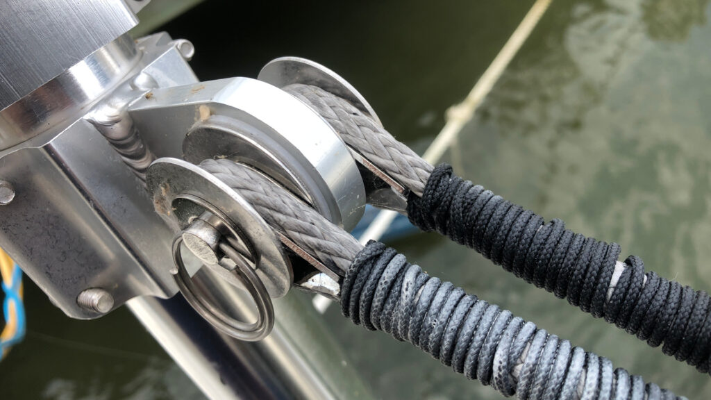
The images illustrate the sequence of assembling the hardware, including the Dyneema line, stainless steel fittings, and the printed washers and pulleys. The Dyneema line was measured and cut to the appropriate length, and the ends were spliced to form secure loops around stainless steel thimbles and wrapped in twine to protect it. The white-ish residue on the twine is whipping compound.
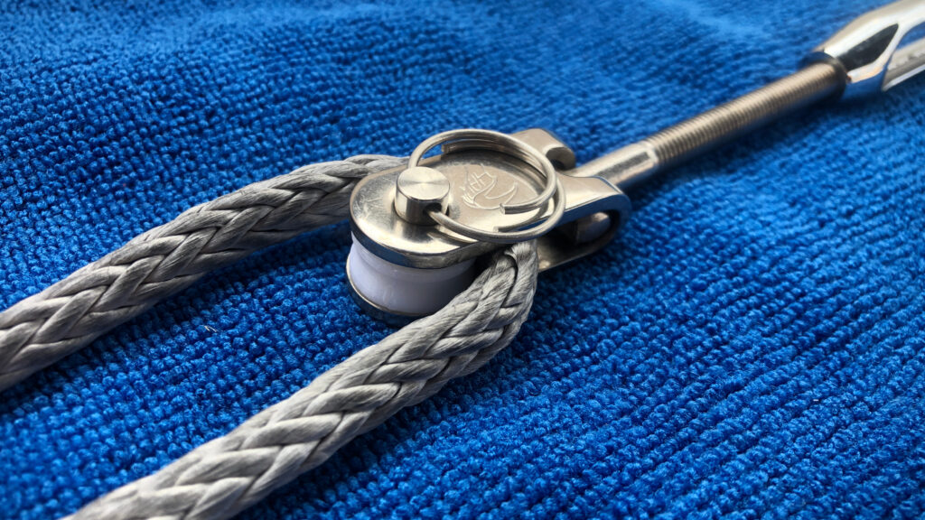
Attaching to the Arch:
The attachment points on the arch were created using clamp-on lifting eyes available from Atlantic Towers. The components were assembled onto the lifting eyes as shown in the images below.
Results
NOTE: These photos were taken before I installed the safety bolts on the forward legs as described above.
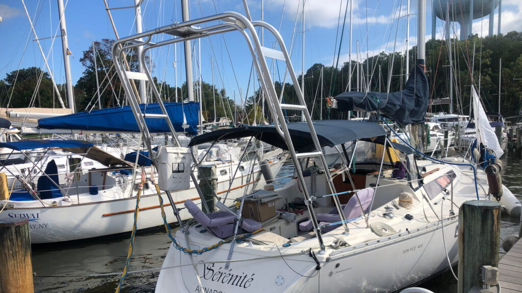
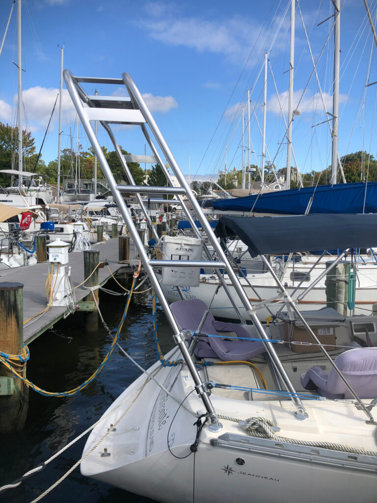
You might be wondering why I left the arch so tall. Well, there are a couple of reasons: 1) The solar hard-top (future project) will use the arch as it’s rear support. In brief, this will be a frame, tiled with solar panels that forms a hardtop over the cockpit. So, the height is to get the equipment that will be mounted to the top of the arch (antennas, radar, starlink dish, windgens, etc.) further back and away from the solar panels to minimize shading. And, 2) to allow mounting of the dinghy tender bar (future project) high so as not to obstruct boarding the boat from the rear when the dinghy is present.
Anyhow, there is only one more piece I need to fabricate for the lifelines: covers to protect the dyneema from the sun. I’ll talk about that in a future post.