Part 1 of a multi-part series documenting the design and development of a 3D-printable optical encoder for sailboat rudder position sensing.
When I started working on SCANS (Sérénité’s Control Automation and Navigation System) for my 1984 Jeanneau Sun Fizz, one of the critical I needed was a way to know the exact position of the rudder at any given moment. SCANS is a distributed software architecture designed to replace proprietary marine electronics with an extensible network of intelligent subsystems—everything from environmental sensing and navigation to real-time robotic control of the rudder and engine. At the heart of the autopilot system lies the rudder actuator: a hydraulic ram that will be controlled by ROS-2 (Robot Operating System, version 2) nodes that demand precise feedback about the rudder’s angular position. This might seem like a straightforward problem, but it turns out that accurately sensing absolute, angular position in a marine environment presents some interesting challenges.
This first post will cover the fundamental design decisions I made and the theory behind why an optical encoder using Gray code turned out to be the ideal solution.
Why Absolute Position Sensing Matters
For rudder position sensing in a marine autopilot, absolute position encoding is essential. An absolute encoder knows its exact position the instant it’s powered on. Each position has a unique code, so there’s no initialisation required. Power cycles, system resets, or electrical noise might cause momentary interruptions, but as soon as the sensor is read again, you immediately know where the rudder is pointing. This is critical for a control system that needs to maintain course through power fluctuations, system restarts, or other disruptions without losing track of the rudder’s actual position.
I considered several position sensing technologies before settling on an optical encoder. The most straightforward option was a mechanical rheostat, essentially a resistive potentiometer that changes resistance as the shaft rotates. This the type of encoder that came with Sérénité when I bought her. These devices are simple and provide an analogue output that’s easy to read with a microcontroller’s ADC. However, they rely on a mechanical wiper contact sliding across a resistive element, which means inevitable wear and eventual failure. In a marine environment where moisture can accelerate corrosion, the reliability concerns made this option unattractive despite its simplicity.
Linear inductive encoders presented an interesting alternative. These devices use an iron core that moves in and out of a coil of wire, with the changing inductance indicating position. They’re robust and non-contact, which is appealing. The mechanical installation is actually simpler than the rheostat—the inductive encoder attaches directly to the midpoint of the steering quadrant, whereas the rheostat requires the rotary wiper to be connected to a shaft with a lever, which is then connected to the quadrant using a push rod. However, the electronics required to drive and read an inductive encoder are more complex than those needed for an optical encoder. The additional circuit complexity and the challenge of implementing absolute position sensing with this technology made it less attractive than the optical approach.
Optical encoders emerged as the most promising solution. They operate without any physical contact, eliminating wear concerns entirely. Unlike inductive encoders, they’re immune to electromagnetic interference. And I have to option of either directly mounting it on the rudder post, or using gears connected by a toothed belt.
Once I’d settled on the optical encoder approach, I considered whether to use limit switches in conjunction with the encoder or rely on the encoder alone. Limit switches at the extremes of rudder travel would provide a mechanical failsafe for detecting end-of-travel conditions—a physical confirmation that the rudder has reached its limits, independent of the encoder’s electronics. This redundancy appealed to me from a safety perspective. Limit switches are robust, reliable, and provide a hard stop signal that the control system can use to prevent driving the hydraulic actuator beyond the rudder’s mechanical range. I decided to include them in the design.
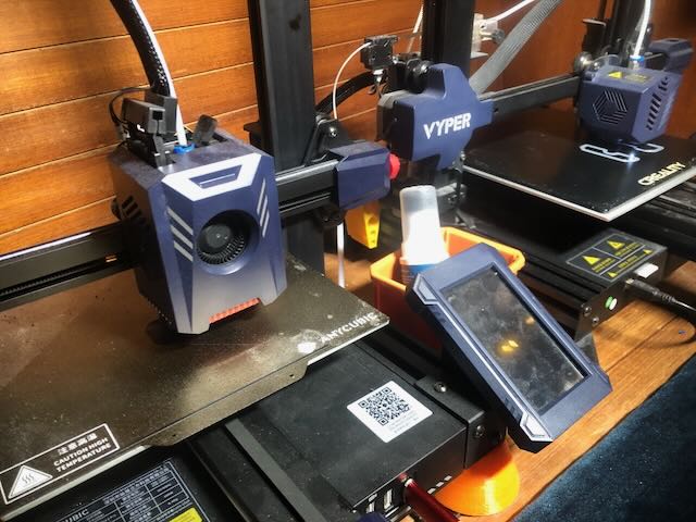
The encoder disk can be manufactured with the onboard Parts Replication System (PRS) aboard Sérénité. The PRS is an additive manufacturing capability inspired by NASA’s work on in-space fabrication for Mars missions—instead of carrying vast stores of spare parts, I carry raw materials in the form of filament (PLA, PETG, nylon, carbon fibre polycarbonate, and TPU) and CAD files. What began as a single AnyCubic Vyper has evolved into a small print farm consisting of two FDM printers managed by OctoPrint running on a Raspberry Pi SBC (Single board microcomputer), with a database cataloguing the many parts I’ve designed.
The system has proven invaluable for creating custom mounts, electrical boxes, deck fills, gaskets, and various bespoke components that would be difficult or impossible to source whilst cruising. For the electronics, I design multilayer PCBs in KiCad and send them out for third-party fabrication. The sensing elements for the encoder—simple infrared LED and phototransistor pairs—are inexpensive and reliable. Whilst optical sensors do require a clean optical path, this is easily achieved with proper housing design. The ability to create an absolute position encoder using readily available components and onboard fabrication methods made the optical approach the clear choice.
Understanding Gray Code
This is where things get interesting. Once I decided on an optical encoder, I needed to figure out how to encode position information in a way that would be reliable and error-resistant.
So, why Not Just Use Binary? My initial thought was to use standard binary encoding, but I vaguely remembered that the optical encoders on old printers and reel-to-reel tape decks didn’t do it that way, though, at the time, why that was escaped me. After some research and experimentation, I remembered that binary encoding has a critical flaw for mechanical systems: multiple bits change simultaneously during certain transitions.
Consider the transition from position 127 to position 128 in binary:
Position 127: 11111110
Position 128: 00000001
All eight bits change at once! In the real world, mechanical alignment isn’t perfect. The sensors don’t all transition at exactly the same instant. This means during the transition, you might momentarily read invalid intermediate values like <code>00000010</code> (position 64) or <code>11111111</code> (position 255). In a control system, these glitches could cause erratic behaviour or even dangerous responses. This is the problem the Gray code was invented to solve.
Gray code (also known as reflected binary code) solves this problem elegantly. It’s a binary numeral system where only one bit changes between consecutive positions. Here’s what the same transition looks like in Gray code: Here’s what the same transition looks like in Gray code:
Position 127: 00000010
Position 128: 00000011
Only one bit changes! This single-bit transition property provides several crucial advantages. If sensors are slightly misaligned, the worst that happens is you read the previous or next position—never an invalid random position. There are no transient invalid states during transitions, so you’re always reading a valid position code. Electrical noise that might cause a brief misread of one sensor only causes a one-position error, not a jump to a random location. As the rudder continues moving, the next valid reading immediately puts you back in synchronisation.
The mathematical beauty of Gray code is in its construction. To convert from binary position to Gray code:
Gray(n) = n XOR (n >> 1)
This XOR operation with a right-shifted version of itself creates the single-bit-change property. Here’s a sample of the 8-bit Gray code sequence showing the first few and last positions:
Position  Binary     Gray Code
   0      00000000   00000000
   1      10000000   10000000
   2      01000000   11000000
   3      11000000   01000000
   4      00100000   01100000
   5      10100000   11100000
   6      01100000   10100000
   7      11100000   00100000
   8      00010000   00110000
  ...        ...        ...
 255      11111111   00000001
Notice how each position differs from its neighbours by exactly one bit. This property holds even when wrapping around from position 255 back to position 0, making it perfect for rotary encoders.
For my rudder encoder, Gray code provides several specific benefits. The single-bit-change property means that vibration, slight mechanical play, or momentary sensor occlusion only causes minimal errors. My encoder disk won’t be perfectly machined since it’s 3D printed; there will be slight variations in track edges, minor warping, and visible layer lines. Gray code means these imperfections won’t cause wild position jumps. If I ever read a position that requires more than one bit change from the previous reading, I know something went wrong and can flag it for error handling. During transitions, I always read either the current position or an adjacent one—never something random—which makes the control system’s behaviour predictable and safe.
The Physical Design
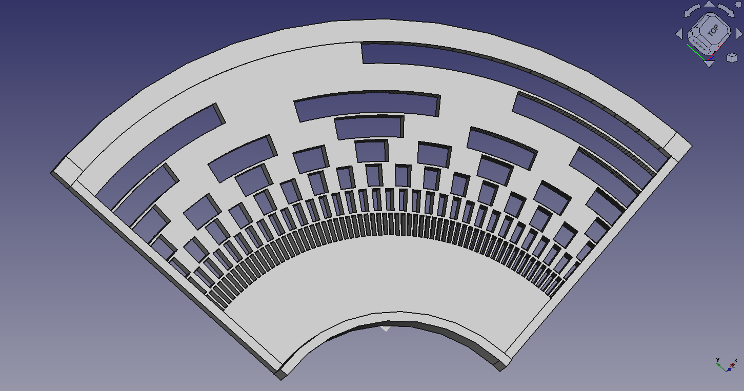
My rudder encoder uses 256 positions (or possibly more) distributed over a full 360-degree disk. Through a gearing arrangement, the 30 degrees of rudder travel corresponds to one complete rotation of the encoder disk, giving me substantially higher resolution than if I’d used a partial disk covering only the rudder’s 30 degree travel arc (Image at the top of the page). With 256 positions over 30 degrees of rudder motion, this provides approximately 0.117 degrees per position—more than adequate resolution for precise rudder control. The encoder disk contains eight concentric tracks—one for each bit of the 8-bit Gray code. Eight optical sensors, each consisting of an infrared LED and phototransistor pair, read these tracks simultaneously. The disk has open slots and solid segments that represent 1s and 0s in the Gray code pattern. As the rudder rotates, the sensors read the pattern and provide the 8-bit Gray code that uniquely identifies each position.
Coming Up Next
In Part 2, I’ll dive into the actual implementation: the mathematics of laying out the tracks, the challenges of making this 3D-printable, the genetic algorithm I used to optimise the design parameters, and the Python code that generates the encoder disk geometry.
But for now, the key takeaway is this: Gray code is essential for creating the error-resistant position measurement system used in rotary position encoders.